MRI magnets and specialist services
MRI magnet shimming: field homogeneity, active and passive correction, and drift
An MRI magnet must do more than reach 1.5 or 3 tesla: it must maintain a uniform field across the imaging volume. Shimming measures and corrects inhomogeneity for the specific magnet, site and application.
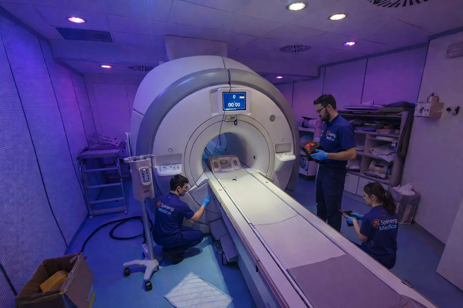
An MRI magnet must do more than generate a very strong field. It must produce an extremely uniform field throughout the volume in which images are acquired.
A magnet can be correctly energised at 1.5 or 3 tesla and still have small field variations from one location to another. This is where shimming is required: the measurements and corrections used to improve the homogeneity of the static magnetic field, B0.
Shimming does not make the MRI “more powerful”. It tunes the spatial distribution of the field so that the local B0 value remains as close as possible to the intended value within a defined volume. The result affects image quality, geometric accuracy, fat suppression, EPI and diffusion sequences, spectroscopy and the reliability of more field-sensitive applications.
Three different activities need to be separated: global magnet shimming, patient-specific active shimming by the scanner, and assessment of field drift over time. Calling all three simply “shim” can lead to the wrong diagnosis and the wrong intervention.
What is B0 field homogeneity?
The MRI main field is designated B0. Ideally it would have the same strength at every point in the useful volume, but no physical magnet is perfectly uniform.
Small differences can arise from:
- magnet winding design and manufacturing tolerances;
- ferromagnetic components and structures at the installation site;
- geometry and size of the measured volume;
- distance from isocentre;
- gradients, bore components and installed hardware;
- temperature, ramp history and field stability;
- the patient, anatomy and interfaces between materials with different magnetic susceptibility.
Shimming does not aim to produce a perfect field everywhere, which is not a realistic physical target. It optimises the field within a specific volume and against the criteria defined for that magnet family.
The Siemens Healthineers Academy defines shimming as increasing static B0 field homogeneity for a particular measurement. The phrase “for a particular measurement” matters: a correction optimised at the centre and over one diameter will not guarantee the same result at the edge or across a larger volume.
From Larmor frequency to image quality
In MRI, proton resonance frequency is directly proportional to the local field. This is the Larmor relationship: when B0 changes slightly in space, the frequency at which protons respond changes as well.
For hydrogen, the frequency is approximately:
- 63.9 MHz at 1.5 T;
- 127.7 MHz at 3 T.
A one-part-per-million difference therefore corresponds to approximately 64 Hz at 1.5 T and 128 Hz at 3 T. This helps explain why the same relative variation can become more demanding for frequency-sensitive techniques as field strength increases.
When different parts of the volume resonate at slightly different frequencies, the effects can include:
- non-uniform fat suppression;
- geometric distortion and displacement in EPI;
- local signal loss or dephasing;
- banding and contrast variation;
- broadened peaks and lower spectral resolution in MR spectroscopy;
- less consistent performance over large fields of view or off-centre anatomy.
Not every artefact is caused by shimming. RF-coil performance, B1 uniformity, gradients, interference, protocol settings, reconstruction and motion can produce similar symptoms. Shimming should be considered when measurements and standardised quality checks show genuine B0 inhomogeneity, not as a generic response to any unsatisfactory image.
How homogeneity is reported: ppm, DSV and measurement method
Homogeneity is often expressed in ppm, or parts per million. A ppm value without further information is incomplete.
Meaningful comparison requires at least:
- nominal magnet field;
- measured volume;
- DSV, the diameter of the specified spherical volume;
- number and distribution of measurement points;
- the metric used, such as peak-to-peak, RMS or VRMS;
- magnet and site condition during measurement.
A magnet will normally appear more homogeneous over a small central volume than over a larger sphere. Peak-to-peak and VRMS also describe different features of the same field map. A statement such as “0.5 ppm” without DSV and method cannot establish true performance or show whether the result is comparable with an OEM specification.
The AAPM Task Group 325 report provides guidance for measuring and evaluating static-field homogeneity. The useful principle for a customer is straightforward: before a correction is discussed, the team must define where, how and against which reference the field is being measured.
What does a shimming activity involve?
Conceptually, shimming connects four stages:
- measure the field at many points in the volume;
- reconstruct a map of deviations from the intended field;
- calculate a combination of corrections supported by that magnet;
- verify the result with another field map.
The shape of the error can be represented mathematically using spatial coefficients, often described through harmonic terms. Software can then estimate the currents or ferromagnetic elements needed to reduce the dominant components.
This does not make the intervention fully automatic. Geometric alignment, measurement volume, field stability, probe calibration, mathematical model, system limits and technical interpretation all influence the outcome. A theoretical correction must always be verified on the real magnet.
Passive and active shimming: what is the difference?
Passive and active shimming are not interchangeable options that can be selected freely. They perform different and often complementary roles.
| Shim type | How the correction is generated | Main function | Characteristic |
|---|---|---|---|
| Passive | Ferromagnetic elements with calculated mass and position, installed in designed trays or locations | Correct baseline magnet inhomogeneity and the stable effect of the site | Fixed and generally stable correction |
| System-level active | Current in dedicated shim coils, sometimes superconducting, depending on magnet architecture | Correct selected spatial components of the field | Adjustable within the available channels |
| Clinical active | Current in gradients or shim coils controlled by the scanner | Compensate the patient and a specific acquisition volume | Calculated for an exam, volume or, on some systems, individual slices |
Passive shimming
Passive shimming uses thin pieces of iron or another ferromagnetic material. Their quantity, thickness and location are calculated so that they deform B0 locally in the direction required to compensate the measured error.
The elements are usually arranged in pockets and trays around the bore or gradient coil. Siemens Magnet Technology patent documentation illustrates the principle clearly: a field plot feeds a model, the model proposes a shim distribution and the resulting field is measured again.
This form of correction is suited to the baseline condition of the empty magnet and its stable environment. It cannot adapt in real time to every patient or anatomy. Access, forces, trays and tooling also differ between magnet families; there is no universal passive shim set.
Active shimming
Active shimming generates corrective fields with electrical current. Depending on the design, correction may be applied through dedicated shim coils, superconducting channels or gradients that also act as first-order shims.
Active systems provide flexibility because current can be adjusted to compensate a particular field component. The number and order of available corrections are system-specific. More channels do not automatically make one magnet better in every situation; what matters is how design, calibration and useful volume work together.
It is also important not to treat active and dynamic as synonyms. An active shim can remain constant throughout a measurement, while dynamic shimming is updated by volume, slice or acquisition phase on systems that support it.
Magnet shimming and patient autoshim are not the same
Installation and service work assess the magnet’s baseline field, normally without a patient, over a defined volume with dedicated mapping instruments. The objective is a homogeneous and documented foundation.
During an examination, the patient locally perturbs B0. Air–tissue interfaces, bone, lungs, sinuses, the abdomen, implants and other materials create subject-specific distributions. The scanner acquires field information in the selected volume and applies a clinical autoshim through its available channels.
Patient-specific shimming is important, particularly off-centre and in field-sensitive applications. It cannot replace global magnet shimming when the baseline field is outside specification. Conversely, repeating passive shimming will not eliminate anatomical perturbations that change from patient to patient.
Teslameter, field gantry and shim camera: their roles
A single isocentre measurement may confirm field strength at that point, but it cannot describe homogeneity across the whole volume. Mapping requires suitable measuring instruments and geometric references.
| Instrument | Function | What it cannot establish on its own |
|---|---|---|
| NMR teslameter | Measures the local field precisely at the probe by deriving it from resonance frequency | A single reading does not certify volume homogeneity |
| Field-mapping gantry | Positions and orients the probe or array at known, repeatable coordinates in the bore | It does not measure or correct the field; it is a mechanical reference |
| Shim camera or magnetic field camera | Combines many probe readings and software to reconstruct a spatial map | It does not insert shims or decide the correct intervention by itself |
Teslameter
Precision mapping often uses an NMR teslameter. Its probe detects the resonance frequency of a small sample and converts it into the local field value. This supports measurements of nominal field, stability, ramping, decay and drift.
Homogeneity requires the measurement to be repeated at known positions or obtained with multiple probes. Each probe also has its own range and tolerance for local gradients; a missing valid reading does not mean that the field is zero at that point.
Field gantry
The expression field gantry is used in service for the positioning structure supporting the camera or probes. It is not the scanner’s cosmetic gantry. The relevant parts are non-magnetic and designed to centre the measurement system and reproduce the map’s planes, angles and coordinates.
If the structure is offset from isocentre or its positions are not repeatable, the software can interpret geometric measurement error as magnet error. Positioning and repeatability must therefore remain within the tolerances specified for the measurement system.
Shim camera
A shim camera is not an optical video camera. In service, the term is often used for NMR magnetic field cameras, such as the Metrolab systems cited here, comprising normalised probes, measuring electronics, software and a support. These arrays can acquire several points at once and, through defined rotations or translations, build a map across multiple planes. Other field-camera technologies may use different architectures.
Metrolab describes its MRI magnetic field cameras as field-mapping instruments used throughout a magnet’s life, from production to installation. Its MFC2046 and MFCTool documentation also explains how measurements are transformed into coefficients supporting passive or active shim calculation.
The simplest distinction is: the teslameter measures the field at the probe, the field gantry provides position and repeatability, and the shim camera turns many readings into a map of the volume.
What affects shimming?
A factory shim configuration cannot be copied unchanged into every building. The final field depends on the combined magnet and site environment and, during scanning, the patient.
Magnet design and system condition
Winding geometry, shielding, available channels, gradient set, bore components, magnet position and mechanical tolerances form the baseline. Ramping, a quench, relocation, major replacement or a change in assembly can justify a new map without automatically implying magnet damage.
Steel and site structures
Beams, rebar, plates, shielding, pipework, floor reinforcement and large nearby ferromagnetic masses perturb B0. The GE pre-installation manual for LCC magnets requires evaluation of the mass and location of steel close to isocentre because excessive steel can degrade homogeneity and system performance.
Later changes to the room also matter. New structural steelwork, equipment, shielding, supports or moving ferromagnetic objects near the magnet can alter a previously stable condition.
Temperature, gradients and temporal stability
Gradient heating, thermal change, eddy-current effects and settling after ramp-up can temporarily affect a measurement. A field plot taken while the system is not stable may describe a transient condition rather than the true baseline.
Patient and acquisition volume
The patient becomes part of the field problem during an examination. Shape, position, respiration, size, implants and tissue susceptibility create local perturbations. DSV, field of view and distance from isocentre also alter the result: a strong central specification does not guarantee identical homogeneity over an off-centre shoulder or a large abdominal volume.
Measurement quality
Alignment, calibration, probe normalisation, point distribution, field stability and correct configuration identification are all part of shimming. More points cannot automatically compensate for incorrect geometry or an instrument used outside its specified conditions.
CXK4, LCC, Mozart, Ludwig, Zebra and OR105: why magnet family matters
Service work uses names that do not necessarily match the commercial scanner model. CXK4, LCC, Mozart, Ludwig, Zebra and OR105 are examples of magnet designs, families or technical names, not shimming methods.
| Family or designation | Prudent identification | Why it must be identified |
|---|---|---|
| GE CXK4 and LCC series | GE families used across different generations; LCC means Low Cryogen Consumption, while CXK4 identifies a well-known high-homogeneity design | Variants, gradient set, passive shim and correction channels cannot be inferred from the GE brand alone |
| Ludwig, Zebra and Mozart | Technical names encountered in service; manufacturer, field strength and configuration must be confirmed from the individual magnet’s documentation | A name used in technical contexts is not enough to infer access, components or shimming strategy |
| Siemens OR105 | A 1.5 T Siemens Magnet Technology magnet, actively shielded and associated with MAGNETOM Avanto | Documentation describes passive shim trays and dedicated handling tools |
The GE SIGNA Creator page describes its CXK4 technology as a high-homogeneity 1.5 T magnet. For OR105, the Siemens Magnet Technology shimming patent explicitly identifies the 1.5 T MAGNETOM Avanto magnet and its passive tray system.
One misunderstanding deserves emphasis: active shielding is not active shimming. Active shielding reduces the fringe field through dedicated windings; active shimming corrects uniformity inside the imaging volume. An actively shielded magnet can therefore also use passive shims.
Before equipment or strategy is selected, the exact magnet family, variant, serial number, nominal field, gradient set, field state and applicable documentation are required. Two scanners with the same commercial name or tesla rating may contain different configurations.
Drift: when the field changes over time
Drift means that the field changes over time, but the term is often used too broadly.
If the whole field changes almost uniformly, the main symptom may be a shift in centre frequency. If the spatial components also change, homogeneity can deteriorate. These are different conditions and they do not automatically require the same response.
Drift can be associated with:
- settling after ramp-up;
- slow persistent-current change;
- thermal condition of the magnet or gradients;
- changes in the surrounding magnetic environment;
- service work, component replacement or movement;
- a technical condition requiring diagnosis.
Drift does not automatically mean reshimming. A uniform change may require restoration or update of the reference frequency. Loss of homogeneity requires comparison of spatial maps. Measurement is what determines whether the response should be active correction, passive reshimming, removal of an environmental disturbance or another technical action.
When should shimming be reassessed or repeated?
There is no universal annual interval for repeating a shim. This does not remove the need for periodic homogeneity checks: AAPM TG 325 recommends annual B0 evaluation, but the recommendation concerns measurement, not automatic reshimming every year. Global magnet shimming should be reassessed when data show a genuine change or after events capable of altering the magnet or its environment.
Relevant situations include:
- a new installation or magnet relocation;
- ramp-down and ramp-up connected with major work;
- a quench or significant cryogenic event;
- replacement of a gradient coil or hardware close to the imaging volume;
- structural changes, shielding or new ferromagnetic masses at the site;
- abnormal drift or deterioration from the acceptance baseline;
- repeatable phantom quality-control failures;
- persistent distortion, irregular fat suppression or EPI problems after other causes have been excluded;
- spectroscopy linewidth moving outside its normal trend.
The first response should not be to run a re-shim function by trial and error. History, baseline, site conditions and repeatable measurements are reviewed first. The assessment may lead to reshimming, but it may instead identify a component problem, an external disturbance, a calibration issue or an exam-specific correction.
Why correct shimming matters
Well-executed shimming protects the physical foundation on which the whole MRI system operates. It can help to:
- maintain uniform spectral fat suppression;
- limit distortion in EPI, diffusion and fMRI;
- improve peak separation in spectroscopy;
- preserve geometric accuracy and uniformity over large fields of view;
- reduce non-diagnostic images and avoidable repeats;
- make calibration and advanced applications more reliable;
- document magnet condition following installation or service.
It does not turn an older MRI into a new scanner, and it cannot repair faults unrelated to B0. Its purpose is to restore the homogeneity that is achievable and specified for the actual configuration.
What does a well-planned assessment look like?
Before work begins, the team should know:
- manufacturer, scanner, magnet family, serial number and gradient set;
- field state, ramp history and recent work;
- any quench, relocation or room modification;
- OEM specification including DSV and metric;
- quality-control data, images and repeatable symptoms;
- previous baseline or field plots;
- compatible measuring equipment and its calibration status.
The result should document central field, measurement volume and method, maps before and after correction, achieved values, final configuration and any residual issue. The useful statement is not merely “the shim was done”, but which condition was measured, which correction was applied and which result was verified.
Safety: this is not an adjustment to improvise
Field mapping and shimming may be performed while the magnet is at full field. Probes and supports intended for the bore may be designed for that environment, while electronic units, amplifiers and other parts of the same camera can contain ferromagnetic components and have field or distance limits.
Passive shims are also exposed to substantial forces. Shim currents, power supplies, leads and access arrangements are magnet-specific. It is therefore unsafe to describe all equipment generically as “MRI safe” or to assume one procedure applies to every platform. Qualified personnel, compatible instruments and OEM documentation are required.
Frequently asked questions about MRI shimming
What does shimming mean in MRI?
It means measuring and correcting small variations in the static B0 field within a defined volume. It does not increase the magnet’s nominal tesla rating.
What is a good homogeneity value in ppm?
There is no universal number. It must be compared with the magnet specification and accompanied by DSV, calculation method and measurement conditions.
Is active or passive shimming better?
They are complementary. Passive shimming mainly corrects the stable magnet-and-site baseline; active shimming provides adjustable system-level or patient-specific correction.
Does the autoshim before a sequence replace magnet shimming?
No. It compensates the patient and examination volume within the available channels. It cannot recover a globally out-of-specification magnet by itself.
If centre frequency changes, must the magnet be reshimmed?
Not necessarily. A uniform field offset must first be distinguished from a change in spatial field shape. Repeated measurements and, when indicated, a new field map are required.
Does the shim camera correct the magnet automatically?
No. It measures and maps the field. Software and qualified personnel use the data to calculate a compatible correction, which must then be applied and verified.
Do active shielding and active shimming mean the same thing?
No. Active shielding controls fringe field; active shimming corrects homogeneity within the imaging volume.
Is the same equipment used on CXK4, LCC, Mozart, Ludwig, Zebra and OR105 magnets?
No. Geometry, field strength, access, trays, channels and configuration can differ. The exact magnet and compatible tools and data must be identified.
Support for MRI field mapping and shimming
Spinergy Medical can support the assessment and planning of field mapping, shimming, ramping and magnet recovery, starting from the installed magnet family, service history, site conditions and measurement results.
Explore our MRI cryogenic services and our article on MRI ramp-up and ramp-down. If you are seeing drift or homogeneity problems, or are planning an MRI installation or relocation, call or write to us so that we can define the case.
This article explains general principles and is not a shimming or safety procedure. Field measurement, shim handling and magnet adjustments must be carried out by qualified personnel using documentation and equipment compatible with the specific system.
Technical sources
- AAPM Task Group 325 — MRI static magnetic field homogeneity measurement and evaluation
- Siemens Healthineers Academy — Introduction to Magnetic Resonance Imaging
- Siemens Healthineers Academy — Management of field uniformity
- Siemens Healthineers — Magnet homogeneity and shimming
- Metrolab — Magnetic Resonance Imaging field mapping
- Metrolab — MFCTool V10 Magnetic Field Camera Software
- GE HealthCare — SIGNA Creator and CXK4 magnet
- Siemens Magnet Technology — OR105 magnet shimming